
Figure 1: Schematic of Split-Hopkinson Pressure Bar (SHPB).
The SHPB comprises a striker bar, an incident bar, and a transmitted bar (Figure 1). A specimen is placed between the incident and transmitted bars, and the striker bar is propelled at a specified velocity, hitting the incident bar and causing compression on the specimen lodged between the two previously mentioned bars; strain gages are implemented to collect the data. Figure 2 is the customized SPHB used for testing porcine brain samples at Mississippi State University (MSU).
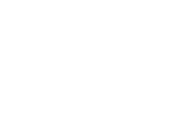
Figure 2: An overview of customized polymer Split-Hopkinson Pressure Bar (SHPB) used for testing porcine brain samples.
Figure 3 depicts harvesting process of samples from porcine brain.
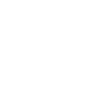
Figure 3: Sample extraction from fresh (< 3 hour post-mortem) from (a) porcine brain, and (b) sample extraction using a 30 mm inner diameter die in the superior-inferior direction, and (c) the sample used for testing.
Table 1 specifies the details of the polymeric bars used in the SHPB setup.
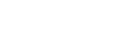
Table 1: Dimensions and material properties of the polymeric bars used in Split-Hopkinson Pressure Bar (SHPB) setup.
The theory for SHPB is based on classical mechanics of elastic wave propagation in the bars and on the principle of superposition of waves. In elastic wave propagation theory, stress, strain and particle velocity are caused due to a single pressure wave (here compressive) are proportional to each other. Hence, knowledge of a single pressure wave at any cross-section of the bars enables us to calculate the wave nature at any other cross-section. A list of the measurement parts used in the SHPB apparatus is given in Table 2.
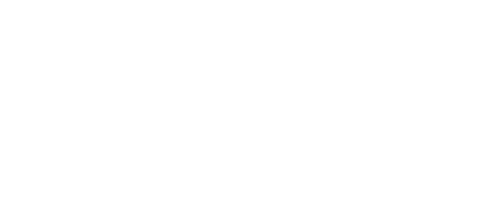
Table 2: Manufacturer details of instruments used for measurement in the SHPB experiment.
Using the knowledge of incident wave and reflected wave at any cross-section and through the principle of superposition, stress, strain and particle velocity can be calculated. Here the stress, the strain and the particle velocity are simply the sum of those related to the incident wave and reflected wave, which are in opposite directions (Zhao and Gary, 1997)
[1]. The specific wave energy, absorbed by the specimen is given by
which is the equation for energy balance. Here Wi is the energy of the incident wave, Wo is the energy of the transmitted wave and Wr of the reflected wave. Stress state homogeneity and balance of input and output are assumed.
According to Zhao and Gary (1997)[1], the following equations are good approximations to calculate the forces and displacements at the ends, which take into account of dispersion and dampening of the waves. Here
where V is the velocity, F is the force, Sb is the cross sectional area of the bar, E Young’s modulus of the incident and transmitted bars, and c is the speed of the wave. Subscript i and o represent variables on the incident and transmitted bars, respectively. The expressions for true strain and true stress are then given as
with
where εt(t) is the true strain, εn(t) is the nominal strain, is the nominal strain rate, ls(0) is the initial length of the sample (undeformed), F(t) is the force, Ss(0) is the is initial cross sectional area of the sample and ν Poisson’s ratio (which is equal to 0.5 for incompressible materials). The above formulae are applicable to compression, with positive strains. The energy absorbed by the sample can then be also calculated as
where the strain rate is given by
The quality of the data can be verified by comparing the energy absorbed by the specimen to the energy calculated from the Equation (1).
References
- ↑ 1.0 1.1 Zhao, H., Gary, G., (1997), “On the use of a Viscoelastic Split Hopkinson Pressure Bar”, Int J Impact Eng, Vol. 19, No. 4, pp. 319-330.


